3
$\begingroup$

TWINKLE is a device devised by Adi Shamir to optimize the sieving step of GNFS. It consists of a cylinder, at the bottom of which are LEDs corresponding to factor base primes which blink with frequency 1/p. If more than a certain number of the LEDs blink at the same clock tick, you've found a GNFS relation (smooth integer pair). This is measured by a brightness sensor at the top of the cylinder: if the light level is above some threshold, the necessary number of LEDs must be lit.

My question is: why use LEDs instead of just measuring current? You could replace the LEDs with transistors that alternate current instead of blinking, and if the current sums to a certain level you have a hit. Why wouldn't this worK?

$\endgroup$
1
  • $\begingroup$ I'm guessing adding up light intensity works better, simpler interaction when you have many sources. Don't need to wire them all together. $\endgroup$
    – Meir Maor
    Commented Apr 18, 2018 at 8:27

2 Answers 2

4
$\begingroup$

TWINKLE uses LEDs as their output is easy to sum. Simply put, the overall light level measured by a photo detector in the top of the tube is the (rough - important) sum of the individual LED emissions. I say important as the overall sum does not have to be accurate. It only has to exceed a threshold level when TWINKLE notifies the controlling PC of the current integer. This ambiguity mitigates the practical issues of light travel distances /times, variations in individual LED emission levels and geometric imperfections of the photo detector's lens.

It's really quite clever. This guy's going to do well for himself. You can add up the output of the device's 100,000 processing cells with a single detector that has clear sight of all of the emitters. The innovation here is that each cell can operate totally independently and an overall 100,000 input adder is not required. It also allows the outputs in the form of light to be send at 10GHz, whereas that's getting ridiculously fast for circa 1999 technology distributed across a 6" wafer.

Your suggestion of adding the currents /measuring the total resistance would require something like this arrangement:-
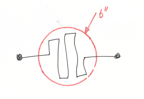
chain

A long chain of 100,000 resistors would have to run between all of the computation cells. To make the maths easy for a sanity check, assume that the wafer is actually square with a grid of 316 x 316 cells. That makes the resistor chain approximately 42m long. The reasons that this can't possibly work are entirely off topic for this site, so here they are:-

  1. You cannot guarantee that any circuit produced on a wafer is viable. In 1999 manufacturers would have been using a ~200nm lithographic process to make this stuff. Adi himself suggests a device yield of 80%. That means it's highly improbable that the resistor chain would be intact without any break or significant thinning. Surprisingly, the yield rate is dropping as technology improves(?) and may be down to 30% today.
  2. It's impossible to measure resistance. You can only detect a voltage or voltage driven current. And any changes in current or voltage have consequences especially if the rate of change is fast.
  3. Contrary to what people think, unfortunately there is no such thing as digital electronics. There is only fast analogue electronics. The implication of this is that electricity can't even travel at light speed, and can be considerably slower (50%c - 80%c). The resistor chain couldn't be longer than ~5mm for transmission line effects to start clobbering the signal at 10GHz.
  4. The same pesky transmission line effects make it impossible to synchronise all the cells to within 10ps - 20ps that Adi requires. Hence the light sensor on each cell.

It's worth noting that TWINKLE's successor, TWIRL, does not use opto summation techniques. This may be an indication of the designer's lack of confidence in the benefits of optical /analogue methods for modern computing

$\endgroup$
3
  • 2
    $\begingroup$ You misunderstood my suggestion. What I'm saying is, each individually operating cell outputs a certain level of current every however many cycles. More precisely, you have 100k resistors in series, and "blinking" is achieved by routing around an individual resistor (all cells have the two paths available). Then you just measure the total resistance. The resistor values would be determined by the prime logs. $\endgroup$ Commented Apr 20, 2018 at 1:21
  • $\begingroup$ @RenéG Ah! What is a typical threshold value for the number of lit cells that counts as a success? $\endgroup$
    – Paul Uszak
    Commented Apr 20, 2018 at 2:52
  • $\begingroup$ Two digits order of magnitude is the best I can say $\endgroup$ Commented Apr 23, 2018 at 18:09
4
$\begingroup$

The main reason is speed. Twinkle's optical adder is much faster than the question's proposed analog adder.

Twinkle's analog optical adder can operate at very high rates, in the gigahertz; much like we can transmit data at high speed over an optical link.

The arrangement proposed in the question, consisting of transistors (or transistor/resistor networks) in parallel, selectively drawing current, with the sum measured at a common point, would only work at much lower speed, due to the distributed capacitance in the common node where the current converges. That distributed capacitance is bound to be proportional to the number of transistors connected, and would severely limit operating speed. To improve speed we'd need to digitize (or at least sample) partial local summations for centralized/hierarchical addition, and poof goes a lot of the simplicity/power-efficiency.

$\endgroup$

Your Answer

By clicking “Post Your Answer”, you agree to our terms of service and acknowledge you have read our privacy policy.

Not the answer you're looking for? Browse other questions tagged or ask your own question.